Build a room-by-room device count before adding a hub
Build a room schedule that keeps lighting counts, accessory counts and documented hub capacity in separate columns.
Updated:
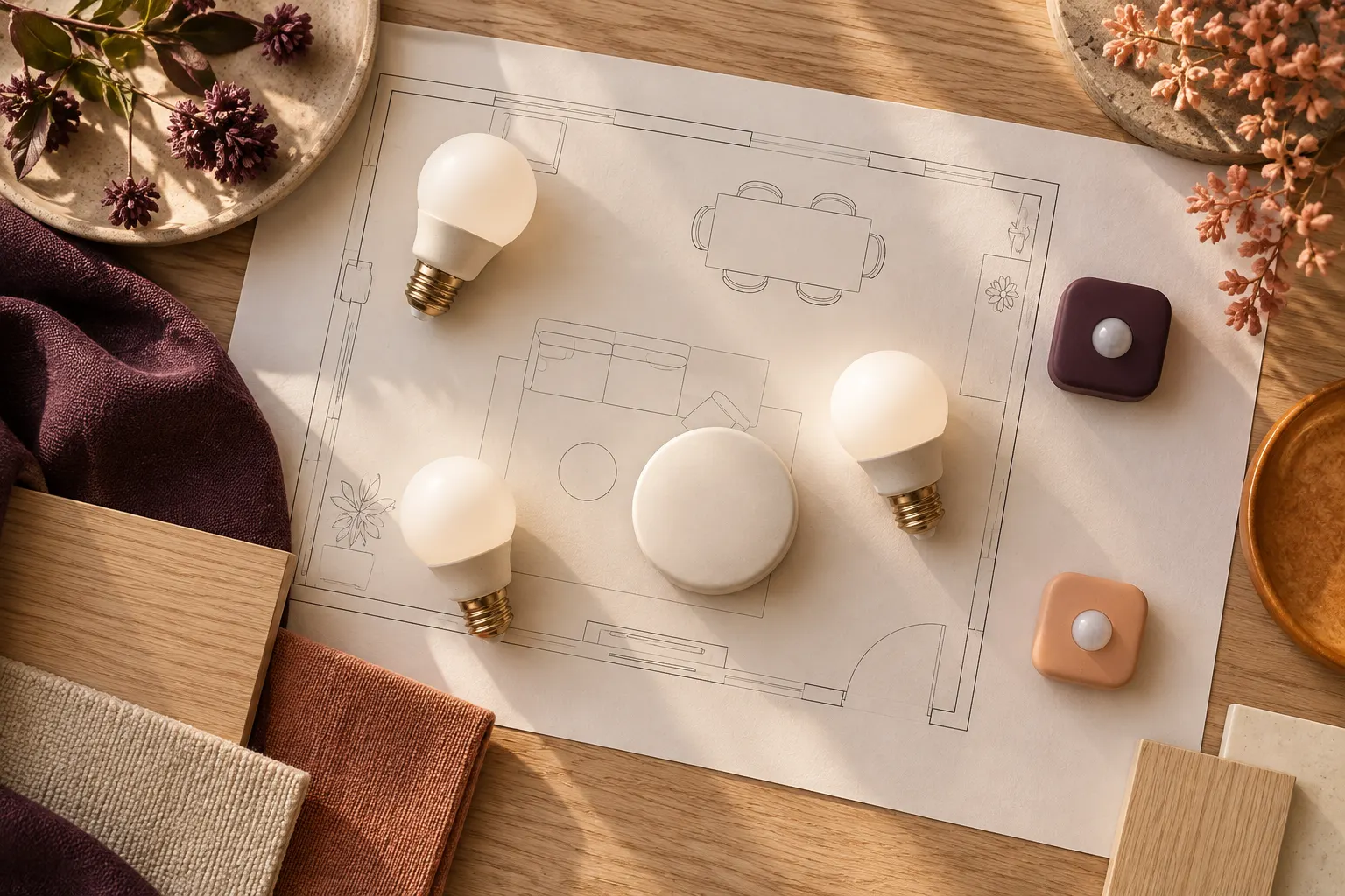
Count two kinds of devices independently
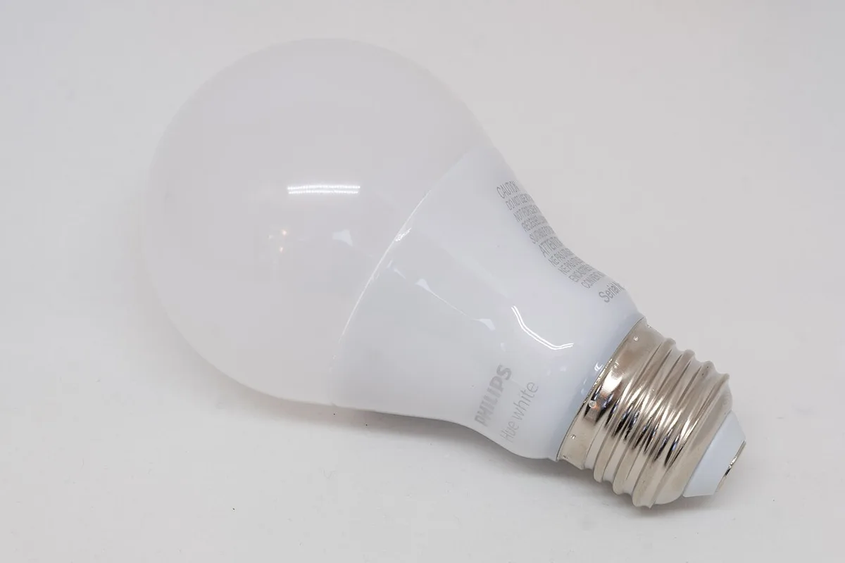
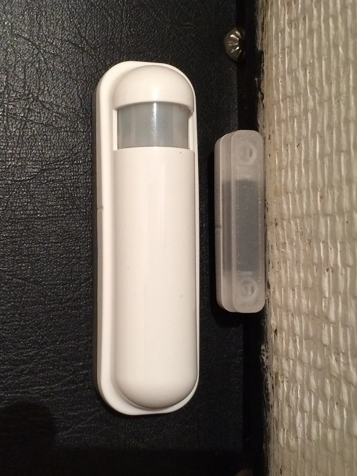
For the documented Hue Bridge 8719514342569, the Australian page lists 50 lights and 12 accessories. A room budget should therefore keep lights and accessories in separate columns. Adding every object into a single total loses the information needed to compare against those separate limits. This article is a counting method, not a compatibility list: putting a third-party sensor on a room sketch does not make it a supported Hue accessory. The real bulb and sensor photographs illustrate different physical device types while retaining their own model and generation limitations.
Give every room one line before adding totals
Write the room name, existing lights, proposed lights, existing supported accessories and proposed supported accessories. Count the actual controlled devices rather than the number of rooms, wall plates or people using the app. Leave uncertain equipment in a separate pending column until the exact hub documentation establishes how it is counted. For example, a proposed motion sensor may require a different hub altogether. That uncertainty belongs in the architecture record, not silently in a Hue capacity calculation. This separation also prevents counting the same item once in a starter kit and again as a standalone purchase.
Work through a complete fictional schedule
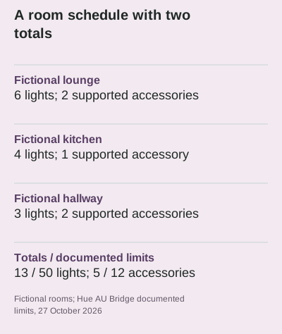
Imagine a lounge with 6 lights and 2 supported accessories, a kitchen with 4 lights and 1 accessory, and a hallway with 3 lights and 2 accessories. The fictional totals are 6 + 4 + 3 = 13 lights and 2 + 1 + 2 = 5 accessories. Against the documented limits, the arithmetic differences are 50 − 13 = 37 light places and 12 − 5 = 7 accessory places. These are available counting places under the example assumptions, not guarantees of radio range, response time or support for unnamed devices. No actual installed system has been tested.
Keep a future addition visible in both columns
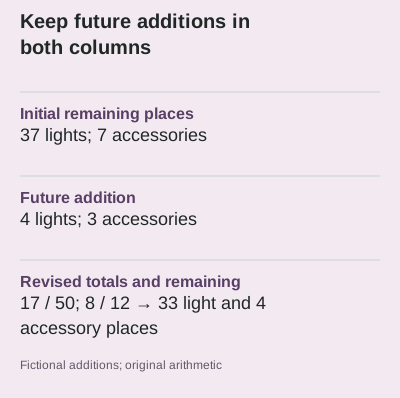
Now add a fictional future room requiring 4 lights and 3 supported accessories. The revised totals become 17 lights and 8 accessories, leaving 33 and 4 places respectively. This shows why an accessory-heavy plan can approach its own limit even when the lighting count looks modest. Use the hub-capacity worksheet on the tools page with the same inputs and compare both results. If an entered total exceeds a limit, the tool reports the excess; it does not choose a replacement architecture or establish that multiple hubs will provide an equivalent user experience.
Review the schedule when the plan changes
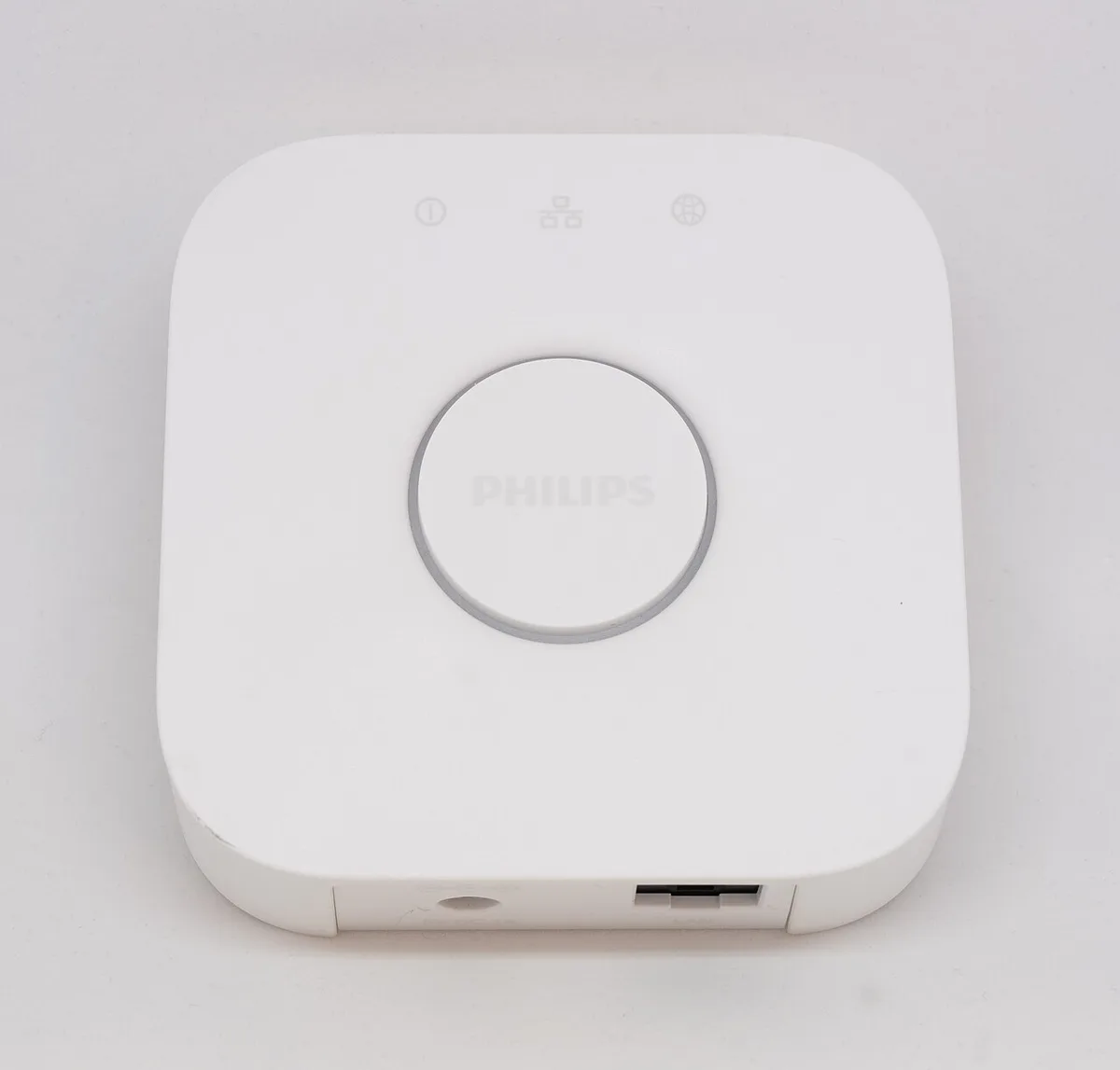
Save the exact Bridge model, the documentation date and the room schedule together. The named Bridge body is documented as 88 mm wide, 88 mm deep and 26 mm high; keep its physical location as a separate record from its device capacity. The archived Bridge photograph identifies a separate controller body, not its current firmware or remaining capacity. A different hub generation requires its own limits and compatibility evidence. Moving equipment between rooms may leave totals unchanged while changing the practical network problem, so retain a separate layout and supported setup record. The finished schedule gives a reproducible answer to the counting question and a clear list of unresolved model questions. It deliberately leaves coverage and performance to evidence that arithmetic alone cannot provide.
Open official model documentation ?